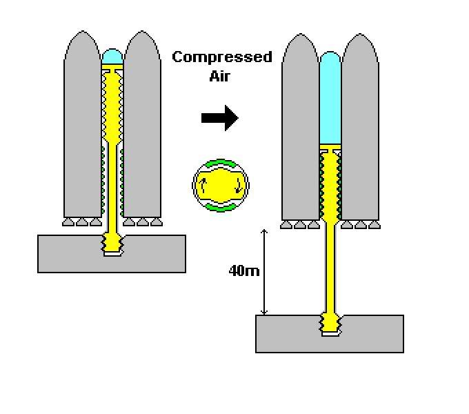
I just thought of a method that could be used to launch it (the following applies to the Paris VII configuration):
Imagine that the triangular space between each tank is filled with solid metal (bare with me for a sec) from the top to bottom. Six of these strucutres will act to connect the tanks together, and they also reinforce the whole launch vehicle. Now imagine that these metal structures are bored from the top down along half their length. The bottom half is similarly bored upwards, but with a slightly reduced bore diameter, until the tubes are connected. The smaller bore at the bottom is then machined with a set of grooves, similar to an internal screw thread. However, once this is done, opposite sides of the grooved bore are machined so that they are flush with the bore of the top tube (i.e. the top bore is extended through the grooved bore in two lines) so that half of the grooved area is removed.

Now, round steel columns will be fitted within each tube.
The lower half of each column will be thinner than the top, encased in insulating concrete, while the top half of the steel column will be machined with a matching array of grooves. These grooves will again be machined in a similar manner, so that they interlock with the inside of the lower tube, but can slide freely within it if they are turned a quarter-turn. A smaller section at the bottom of the column will also be machined with these grooves.
At the very top of each column will be a piston which can slide freely within the upper half of the tube and seals against it. Once the columns are fitted by lowering them through the top of the tube (with the column turned a quarter-turn so that it can slide all the way in), a cap is fitted to the top of each tube to seal it. This then creates an air-tight cylinder from which the column can act as a piston.

For additional support, another six tube and column assemblies can be mounted around the periphery of the launch vehicle. Now, at this point I should point out that these tubes will probably not be made out of solid metal, but rather some sort of lighter-weight design will be used.
This is how the vehicle might be assembled in the VAB:
First, a few tube-and-column assemblies are mounted upright onto the MLP platform. For each column, there will be a short bore with interlocking grooves bored into the MLP platform directly beneath it. This is so the bottom section of each column can be lowered into it, and when quarter-turned, they will lock with the MLP. Once a few tube-and-column assemblies are affixed to the MLP, the huge tanks (complete with engines) can be brought in one at a time and bolted to the tube-and-column assemblies. Thus the columns will act as supports as each tank is added, keeping their engines off the ground.
Once all 12 tube-and-column assemblies, and all 7 tanks (including payload), are affixed together, the completed launch vehicle can be rolled out of the VAB using the existing crawler-transporters.
Now heres where it all comes together:
Once the vehicle reaches its designated launch site, the crawler transporter stops, and compressed air is pumped into the top of each tube. At this point, the columns are still locked within the tube and the MLP, but once sufficient pressure is built up to support the dry weight of the launch vehicle on air pressure alone, each column is turned a quarter-turn, unlocking them. Air continues to be pumped so that the vehicle is eventually lifted right into the air; so far that the piston at the top of the column is at the bottom of the upper (smooth-bored) tube. At this point, the columns are again turned a quarter-turn, locking them to both the MLP and the launch vehicle.
All of the vehicles 49 engines are now so far up in the air (maybe 40 meters above the surface of the MLP) that there will be no need for blast diversion channels or any sort of permanent launch pad structure (although a traditional launch tower will probably be maintained for crew loading, systems monitoring, fuel management, and the like).
With all 12 columns locked to the MLP and vehicle, the fuel tanks can now be filled in preperation for lift-off. All 49 engines can then be tested for a few seconds while the columns hold the vehicle down. If all engines are go, all 12 columns are quickly quarter-turned (perhaps explosively); instantly releasing them from the launch vehicle.

To aid their quick release, the grooves may be helically cut at a 45-degree angle: perhaps clockwise at the bottom and anticlockwise at the top, so that when they are turned, the acceleration of the vehicle provides some of the force needed to turn them, and also so that the columns remain anchored to the MLP when they are unlocked from their tubes. Also, the pistons at the top of each column will be designed to safely shear off when the launch vehicle is released.
The four first-stage tanks will each bring with them 2 tube assemblies, and 2 extra engines (in addition to their own 7 engines), when they are spent and released. The two second stage tanks will shed the remaining 4 tube assemblies, so that the middle tank carries no additional mass to orbit.
